
A drawing labeled “machined enclosure” can look complete right up until the quote arrives with questions about connector cutouts, sealing faces, cosmetic surfaces, and inspection points. Those questions are not busywork. They are where an enclosure RFQ either becomes buildable or turns into a string of assumptions that surface during first article review.
For a CNC-machined unibody enclosure, the useful specification is not just a 3D model. You need to define what the enclosure must interface with, which dimensions control fit, how the part will be inspected, how many parts you need now and later, the finish, and the delivery requirements.
The short answer: specify function, geometry, inspection, quantity, finish, and delivery
Give your custom CNC enclosure manufacturer six things: the intended function, released CAD and drawing files, critical datums and tolerances, inspection and material-document requirements, prototype and production quantities, and finish and shipping instructions. That is the shortest answer.
Start with function because it decides what matters in the geometry. A pocket for a PCB, a gasket land, a threaded mounting point, a connector opening, and a heat-transfer surface do not carry the same risk. Then make the drawing govern the features that cannot be inferred from CAD: thread callouts, surface-finish requirements, dimension limits, datum references, and cosmetic restrictions.
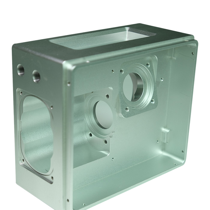
DS Industries provides CNC milling and turning alongside other manufacturing processes, and its CNC-machined unibody enclosure is identified as a 5-axis-milled part. That makes the quality of the RFQ especially consequential: multi-face machining can reduce setups, but it does not remove the need to define how the part will be located and checked.
Design the enclosure around functional interfaces, not just its outer shape
An attractive outside profile is rarely the hard part. The costly problems tend to be inside: a board that rocks on bosses, a USB connector that sits off-center in its opening, a cover that distorts over an uneven sealing land, or a screw that bottoms before it clamps. Mark the interfaces that drive those outcomes.
Identify the board mounting pattern, connector locations, fastener type and thread engagement requirement, mating cover or panel, cable-entry features, and any surfaces expected to transfer heat. If aluminum is your chosen material, specify the alloy and temper rather than writing only “aluminum.” If the enclosure will receive a coating, state which dimensions must remain masked or compensated; coatings can affect thread fit and close-clearance interfaces.
Also state which faces are cosmetic. “No visible tool marks” is too vague to inspect. Use your drawing or a reference sample to identify the show surfaces, acceptable tool-path direction if relevant, and areas where witness marks or clamping contact are prohibited. A machining shop cannot reliably protect a surface it has not been told is visible.
When 5-axis milling is worth considering for multi-face enclosure geometry
5-axis milling is most useful when enclosure features live on several faces or relate to one another at angles: side connector ports, angled pockets, compound exterior forms, and features that would otherwise require repeated re-clamping. The machine can orient the workpiece to reach those areas in fewer setups, which can help preserve relationships between faces and avoid access problems.
It is not automatically the lowest-cost answer. A simple rectangular housing with top-side pockets and ordinary side holes may be more economically machined with fewer axes. Ask the supplier which features actually require simultaneous or indexed multi-face machining. The point is to choose the process for the geometry, not to add complexity because the term sounds premium.
Make critical dimensions traceable from drawing datums to inspection
Every enclosure has dimensions that are merely informative and dimensions that decide whether assembly works. Put the latter on the drawing with datum references that match how the part will be located in assembly and inspection. For example, connector position should be controlled from the mounting surface or board-location scheme that governs the real assembly—not from a convenient exterior edge that has no functional role.
Define the critical-to-function features early: mounting-boss locations, thread axes, connector cutout positions, mating faces, wall thickness where it governs clearance, and flatness or profile requirements where a cover or gasket must seat. Do not apply an unnecessarily tight general tolerance across the whole model. It drives machining and measurement effort into features that may not need it, while still failing to explain what truly must line up.
For a low-volume CNC enclosure, this discipline pays off before the first part is cut. The supplier can build an inspection approach around the same datums your team uses at incoming inspection. That makes a dimensional report useful instead of a page of disconnected measurements.
What to request from DS: CMM inspection, dimensional reports, First Article Inspection, and material certificates
DS states that it can provide dimensional inspection, visual inspection, CMM inspection, requested First Article Inspection, and material Certificate/Test Reports. Request the items that answer a real acceptance question; listing every document by habit adds time without necessarily reducing risk.
- First Article Inspection: request it when the part is new, the assembly fit is sensitive, or your team needs approval before the remaining quantity proceeds.
- CMM inspection and a dimensional report: identify the drawing dimensions and datums you want reported. “CMM report required” alone does not say which features are critical.
- Material Certificate/Test Report: request it if material identity, traceability, or a specified material condition matters to your program.
- Visual inspection: define the cosmetic surfaces and acceptance standard, especially on an exposed machined enclosure.
Plan prototype and production orders as one sourcing decision
A prototype order answers more than “can this shape be machined?” It should expose tolerance conflicts, tool access limits, assembly sequence problems, and finish decisions before those issues multiply. Send the expected next-stage volume with the prototype RFQ, even if the number is only a planning range. DS describes its services as supporting flexible small-batch production and customized mass production, so the intended order path can affect the manufacturing recommendation.
Keep the prototype configuration disciplined. If you approve a first article with one thread specification, surface treatment, or inspection scheme and change those later, it is no longer the same validated part. Record the drawing revision, CAD revision, material callout, finish, and approved deviations on the purchase order.
What can change between low-volume CNC prototypes and customized mass production
The part’s functional requirements should not change, but the production plan may. Shops may revise workholding, tool selection, inspection sampling, packaging, or operation sequence as quantity rises. Those changes are normal if the released drawing and acceptance criteria remain the authority.
Buyers often overlook packaging. A bare machined part may survive one shipment differently than a finished cosmetic enclosure with exposed edges and visible faces. State any separation, protective-film, labeling, or lot-identification needs before production starts. For the part geometry itself, review DS’s Unibody Enclosure machining approach against the actual interfaces in your design rather than treating a gallery example as a universal specification.
Close the RFQ with finish, documentation, and U.S. delivery instructions
Finish is a manufacturing requirement, not a line to settle after machining. Name the finish system, color or appearance requirement if applicable, masking areas, thread protection, and any surfaces that must remain bare for electrical contact, bonding, or thermal contact. If you have a finish sample or approved color reference, include it.
Then make the RFQ operational: list the file formats, drawing revision, required documents, requested approval point, quantity by revision, ship-to address, consignee contact, and desired arrival date. DS states that low-volume orders can be shipped to U.S. customers by FedEx. Confirm the shipping method, Incoterms if your company uses them, customs information, and who receives tracking updates instead of assuming those details will be resolved after parts are packed.
FAQ: Can a CNC-machined enclosure itself be claimed UL, CE, RoHS, or FCC compliant?
Usually, no—not as a blanket claim based on machining alone. UL, CE, and FCC obligations generally concern a finished product, component category, or system evaluated against the applicable requirements. RoHS concerns restricted substances and requires appropriate material and process evidence. A machined enclosure can support your compliance program, but it does not make the assembled electronics product compliant by itself. State the documentation or material restrictions you need, and have the final product claim reviewed against the rule or standard that applies to your market.
FAQ: What information affects CNC prototype lead time and shipment to the United States?
Released CAD and drawings, material availability, geometry, tolerance complexity, finish, inspection requirements, first-article approval timing, order quantity, and shipping instructions all affect timing. Missing data is often the avoidable delay. Send one controlled RFQ package with your revision level, requested documentation, finish callout, destination, and approval path. That gives DS a defined basis to quote the prototype and plan its shipment rather than filling gaps with assumptions.